
For some time now myself and my father have been pondering on the idea of converting our Massey Ferguson 165 made in 1969 into 4wd. This idea first came to us when we needed a 4wd tractor to work the land, so our ambition was to convert our Massey into for 4wd. The purpose of this blog is to help me keep tract of all the information there is out there to do the conversion, and also to track my progress.
Archives
All posts by 4wd Massey Ferguson 165
A number of companies produced four-wheel-drive kits for converting Massey Ferguson and other tractors into four-wheel-drive. One of these companies was 4 Wheel Traction.
Four Wheeled Traction Ltd was a firm that built a few 4-wheel drive conversion of tractors and other vehicles. The Firm was based at 15 North Audley Street, London. Basically little is known, the firm supplied Kits of parts for dealers to convert tractors to 4-wd, using a sandwich transfer box that added 6″ (150 mm) to the tractors length and a new front axle, assembly with steering links and a Prop shaft to provide the drive. The conversions were supplied as a complete kit for the Dealers to fit to new or used tractors. The company made the 4-WD axle conversions for tractors to fit Massey Ferguson 100 series tractors, 165, 168, 175, 178, 185, and 188, and the later Massey Ferguson 500 series 565, 575, and 590 models, from 1976.

Massey Ferguson 165 Convered To 4wd Using A 4WT Conversion Kit
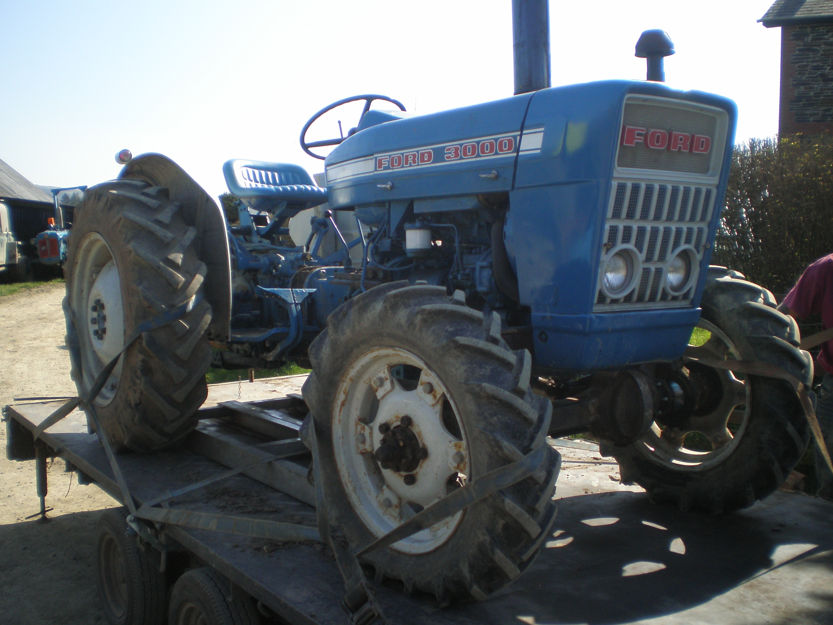
All Grip Traction is a recently formed company designed at converting small two wheel drive vintage tractors into four wheel drive. This small company converts a range of classic tractors including the Massey Ferguson 165 into 4wd. This is the only company that is still in existence today which carry out this conversion. So far the company has successfully converted a Fordson Dexta, Super Dexta, Ford 3000, Ford Ferguson, Ferguson T20, Massey Ferguson 35 and 65.
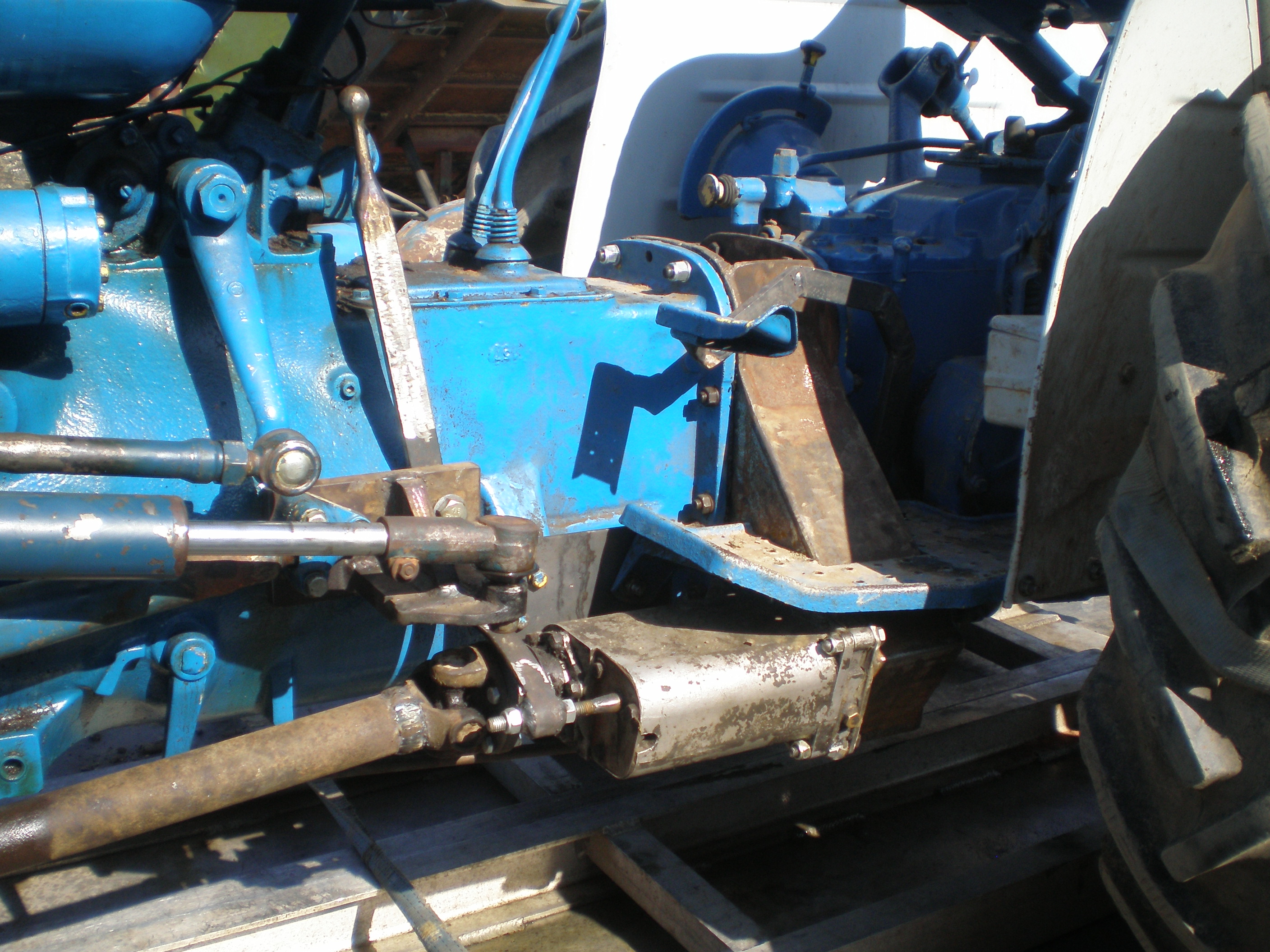
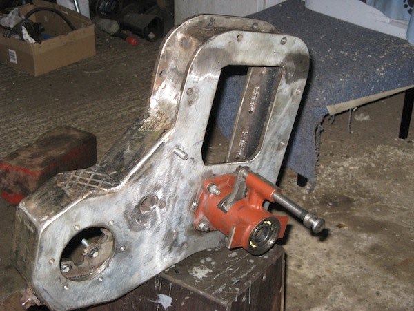
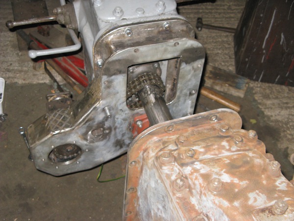
As can be seen from the pictures above, the construction and design of the 4wd transfer case and the 4wd front axle is poor in my opinion. The main problem I have with this solution to the problem is the fact that the transfer case uses a chain to transfer drive from the main output shaft from the gearbox to the transfer shaft which sends power to the front wheels. This method of using a chain would not be suited for heavy work like a tractor would do.
The second problem I have with this conversion is that the front axle that is used in the conversion is of poor design. The axle has been modified off the back of an old Land Rover jeep, the axle is first chopped to size (length ways) and two differential swivel ball joints are added at each end to all for steering the tractor.
The problem here is that the swivel ball joints tended to cause problems when locking the steering causing, in some cases, the ball joints to pop out of its sockets. Also the poor design of mounting the axle to the tractor seems to me like a “botch job”, the existing 2 wheel drive axle is welded to the 4 wheel drive axle, and the mounting brackets are the used on the 2 wheel drive modified axle to connect the assembly to the tractor.
Firstly the aesthetics of the front completely distracts the eye from the profound iconic look of the 100 series tractor as well as this the mounting brackets used on the 2 wheel drive axle was not designed to carry the extra loads and stresses from the 4 wheel drive axle. This is certainly not good when a good reliable tractor is required to do a job and the conversion doesn’t hold up.


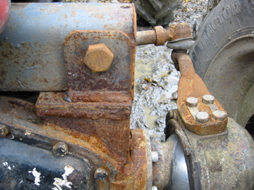
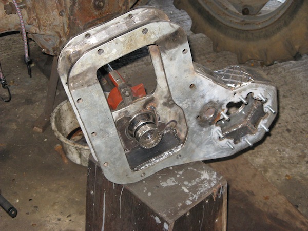
As can be seen from the above photos this second design is no better than the first, and I would even go to say that it is worse. The big issue here is the transfer case is no longer located in between the gearbox and the centre housing but instead it takes its drive from the PTO shaft. This essentially means that 4wd can only work if the PTO is set for ground drive, so while using the tractor in 4wd you cannot use the back PTO for cutting grass, topping, spreading slurry or for anything that requires the PTO to spin at engine speed. This is the major flaw of this design.
All in all I can say that i will not be using the design for the conversion of my tractor as the cons far out weigh the pros.
If more information is required about the services that this company provides a link is provided here, All Grip Traction.
After long periods of time searching the internet looking for a conversion kit that will suit my tractor I came across a forum in which I asked for any information in relation to the company 4 Wheel Traction whom made the conversion kits for the 100 series tractor. Thinking that I would not get a reply back I acquired a 4wd parts manual which may help in my understandings on how the system works. Below shows the parts manual:
4wt Conversion For Massey Ferguson
Having looked at this parts manual its still unclear on exactly how the box works. My initial idea was to, hopefully manage to get the conversion kit first, then learn the inner workings of the design, but unfortunately this is much easier said than done. There is only some much you can learn from looking at drawings and manuals.
I believe that I may be making progress in terms of sourcing the conversion kit. I was given a number of a guy called Anthony in England who bought all the remaining parts from 4 Wheel Traction Ltd when they closed down in the 80s. I got in contact with Anthony today and there is hope of getting the conversion kit. Unfortunately he has not got the transfer case to suit my tractor as he explained that the splined shafts in the early Massey ferguson tractors contained, what is know in the industry as a core splined shaft.
The later models contains a fine splined shaft. But he did say that he is waiting on the core splined transfer case to come in, so I will be keeping in contact with him. One thing I must do is to look at the different shafts and splines to see what the differences are, then this might point me in the right direction to where I could possibly carry out the conversion.
For the past 2-3 weeks I have been researching the coarse spline shaft that is in my tractor. I found out that Massey Ferguson tractors built before 1971 all have core spline shafts in them. A spline is basically in layman terms a gear cut onto a shaft. Coarse refers to the size and type of splines (like teeth on a gear) on the shaft.
Usually coarse spline shafts have up to 9 or 10 splines and are gennerally on small shafts. The splines are usually big and bulky and can have an effect on the performance output as well as the size of force the shaft can withstand. The material strength is a similar issue to bolts: Mild steel bolts are like putty, all the ones in our cars are high tensile of varying grades, some stronger than others depending on the application.
The ultimate strength of a bolt is reflected in what torque it should be tightened to so if we look at 3/8 UNF bolts in MGA/B/Midget as an example, the more normal high tensile bolts torque to about 30 lb-ft, head studs 45-50 lb-ft, and crown wheel bolts to 60 lb ft. Halfshaft and gear box component steels have a similar range. Shown below is what a coarse spline shaft looks like:

The other part of the strength equation is the design. The performance of a halfshaft of a given material is influenced by two primary considerations. The root or core diameter (that’s the diameter of the base of the splines) and the concentration of stress. If a given amount of stress is concentrated into a smaller area then the shaft is more heavily loaded and more likely to fail.
The standard halfshafts of the early Massey Ferguson tractors like the 20, 35, 65 are the worst possible design:
The large square, coarse spline form reduces core diameter and also focuses stress into the centre of the halfshaft, while having the spline cut into it, it causes further stress raiser at the end of the spline. Waisting the halfshaft down to the root diameter is a good way of optimising the strength of what comes standard. It’s not so much that removing metal makes it stronger, it’s that it spreads the stress along a greater length of halfshaft thus reducing the concentration of stress substantially.
Fine spline is based on the same concept except it holds a greater number of splines (like teeth on a gear) and is generally on a bigger shaft.
Other design features which reduce stress concentration substantially are finer splines, v-shaped splines, and also the splines being formed by rolling, as per the later Massey Ferguson halfshafts.
A further advantage of the fine spline form is that the core diameter is increased about 20%, giving directly a similar increase in strength. Shown below is what a fine spline shaft looks like:

A common misconception is that harder halfshafts are needed. While a certain degree of hardness is required of course to withstand the load applied to the spline without it wearing away, hardness isn’t the issue, it is the core strength of the material that’s important. The stronger steels also tend to be harder, but aren’t hardened as such, they can still be cut and machined etc.
Just an undated to confirm my research in relation to the differences and looking at the reasoning behind the need for the fine spline shafts over the coarse shafts. I came across a forum where a chap was wondering if coarse spline or fine spline is better. Shown below is a screen grab on his findings from the technicians on the site:

I also came across a book which explains in good detail what splines are and why they are used:
“A splined shaft is a shaft having multiple groves, or key-seats, cut around its circumference for a portion of its length, in order that a sliding engagement may be made with corresponding internal groves of a mating part.” Engineering Drawing & Design, Cecil Jensen.
Splines are capable of carrying heavier loads than keys, permit lateral movement of a part, parallel to the axis of the shaft, while maintaining positive oration, and allow the attached part to be indexed or changed to another angular position.
Splines have either straight-sided teeth or curved-sided teeth. The latter type is know as an involute spline.
Involute Splines:
These splines are similar in shape to involute gear teeth but they have pressure angles of 30, 37.5, or 45. There are two types of fits, the side fit and the major-diameter fit.Major diameter fit spline is suitable for applications where axes alignment between two parts (internal and external spline) is a critical design parameter.
There are certain manufacturing challenges when dealing with major dia. fit splined couplings, mainly, the restrictions associated with the precision grinding of the internal spline’s major diameter. In some cases this may not even be possible taking into the account the grinding wheel diameter and the amount of space required for the grinding head.

Side fit splined couplings are widely used in all industries including automotive and aerospace. The main feature of this type of coupling is its self-centering ability under load. Although not as precise as the major diameter fit spline, this type of coupling serves successfully in a wide variety of applications. In some cases, to improve the axes alignment and reduce vibrations the spline pilot diameters are introduced.

Straight-Sided Splines
The most popular are the SAE straight-side splines shown below. They have been used in many applications in the automotive and machine industries. Involute Splines are favoured over straight Sided Splines because of their greater strength and the fact that for any given pitch the tooling can cut any number of teeth resulting in a more cost effective production method.

Serrations
Serrations are shallow, involute splines with 45 pressure angle. They are primarily used for holding parts, such as plastic knobs, on steel shafts.
Today after waiting to hear back from Anthony about the 4 wheel drive Dropbox which will suit my tractor, I decided to ring him. during our conversation I asked if he had got in the dropbox but unfortunately he said that there was an issue with the seller and therefore, cutting long story short, he couldn’t sell me what he didn’t have.
One the other hand he did say that if I could get my hands on a 4 wheel drive Massey Ferguson 265 or 290 I would be able to swap over the 4 wheel drive components onto my tractor. He did say that there might be an issue with the prop shaft hitting the sump but he wasn’t certain and that the different splined shafts would cause a problem when connecting the dropbox to the gearbox but he said that I could swap the gearboxes as well which would solve this.
So now failing that I will not be able to source an original 4 wheel drive conversion kit for my tractor I will have to look into the possibility of swapping over the Massey Ferguson 265 or 290 components to convert my 165.
I opened up a forum on Yesterdays Tractor, link to the forum here, asking the question on how to convert a MF 165 into 4wd, to my surprise the original conversion kit was not very good, the steering lock was shockingly bad and the ball joints had a tendency to slip out of there sockets when on full lock.
I confirmed that a MF 265/290 swap over would work, but I will have to check that the 265/290 has the same coarse splined shaft running through the gearbox and centre-housing before I consider undertaking this solution.

